
 Every Mechanism
Home How a Rotary Engine Works
Every Mechanism
Home How a Rotary Engine Works
Most car engines push pistons up and down. A rotary engine has none: a three-sided rotor spins inside a housing shaped like a fat figure of eight. Its three faces make three chambers that each draw in air and fuel, squeeze it, burn it and push it out, again and again.
Video
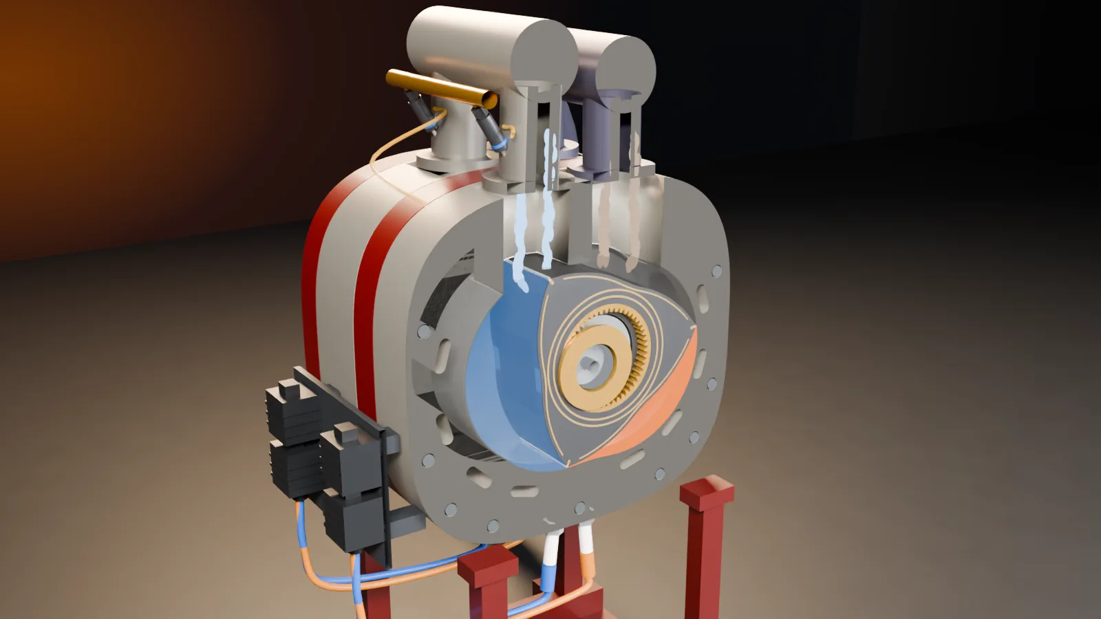
A twin-rotor engine, cut open at the front. Open the throttle and watch the rotor turn, the shaft spin three times as fast, and each chamber change colour through its four strokes. Drag to turn the view, scroll or pinch to zoom, and click a part.
The whole engine laid out on the workshop floor: the housings across the back, in order from front to rear; the gears, the two rotors, the eccentric shaft and the flywheel in the middle; and in front, the systems that feed it, fire it, oil it, cool it and let it breathe out. Tap any part or pick a name below.

Hover or tap the picture. Amber rings mark every part.
The front rotor seen face-on, with the front of the engine cut away. One chamber is filling with air and fuel on the left, one has just been fired at the bottom right, and the third is pushing out its exhaust at the top. The numbers follow the flow: in through the intake, round with the rotor, the spark, out through the exhaust, then the gears and the shaft that turn it all, and the housing.

Blue: air and fuel coming in. Orange: the mixture just after the spark. Grey: burnt gas on its way out.
The same steps as the video. Each picture is a moment from it; press Show me in 3D to set the model up for that step.

Drag the rotor round, or press Run. Follow one face through its four strokes, watch its chamber grow and shrink twice in every turn, and count: the shaft goes round three times for each turn of the rotor.
The rotor’s three tips never leave the wall, so its faces always make three separate chambers. Each chamber is smallest at a waist of the figure of eight and largest at a lobe. On its way round it passes the intake port, the plugs and the exhaust port, so it does all four strokes in one turn of the rotor.
The burning gas pushes on the rotor’s face. Whatever the face’s shape, that push always points straight through the rotor’s centre, and the centre sits on the lobe, 15 mm off the shaft’s axis. So the push turns the shaft like a hand on a crank.
Each rotor tip carries a thin steel apex seal, pressed against the wall by a spring and by the gas behind it. Wear one out and the gas leaks past it into the next chamber. Run a compression test and see which faces it hurts.
A rotary’s compression test reads every face: three pulses for each turn of the rotor. Mechanics crank the engine with the starter and compare the readings at about 250 rpm, because a leak loses more the more time it has. At running speed the same leak costs less, but it still costs power.
Every face gives one power stroke per turn of the rotor, so one rotor gives a push every turn of the shaft. Two rotors half a turn apart give two, as many as a four-cylinder piston engine, but each push lasts three quarters of a turn instead of half. See how smooth the turning force is, and how much the flywheel has to do.